How Long Should It Take to Read an Mpu6050 With an Arduino
Remember when we were kids, the gyroscopes at scientific discipline off-white always fascinated united states of america every bit they move in peculiar ways and even seem to defy gravity. Their special properties brand them extremely of import in everything from small RC Helicopters to the advanced navigation system on the space shuttle.
Did you know?
Russian Mir infinite station used eleven gyroscopes to maintain its orientation to the sun. The Hubble Infinite Telescope has six navigational gyros that assist ensure that the telescope maintains correct pointing during observations.
In recent years, some crafty engineers successfully fabricated micromachined gyroscopes. These MEMS (microelectromechanical system) gyroscopes have paved the manner to a completely new set up of innovative applications such as gesture recognition, enhanced gaming, augmented reality, panoramic photo capture, vehicle navigation, fitness monitoring and many more.
No doubtfulness the gyroscope and accelerometer are dandy in their ain way. But when we combine them, we can become very accurate information about the orientation of an object. This is where the MPU6050 comes in. The MPU6050 has both a gyroscope and an accelerometer, using which nosotros can measure out rotation along all 3 axes, static acceleration due to gravity, also as motion, shock, or dynamic dispatch due to vibration.
Before nosotros apply the MPU6050 in our Arduino project, it would exist good to run across how accelerometers and gyroscopes actually work.
How Accelerometer Works?
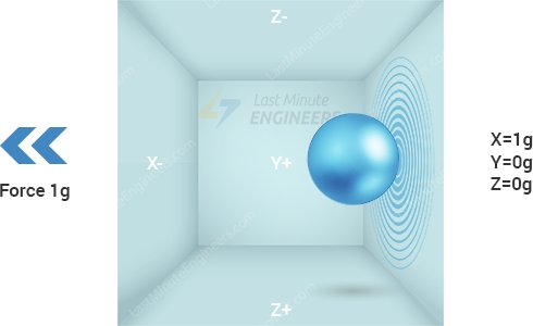
To know how accelerometers work, it is oftentimes useful to imagine a ball inside a 3D cube.

Suppose, the cube is in outer-space where everything is in weightless state, the ball will simply float in the centre of the cube.
Now let's imagine each wall represents particular axis.
If nosotros all of a sudden move the box to the left with acceleration 1g(A single G-force 1g is equivalent to gravitational acceleration 9.eight chiliad/southward2), no dubiety the ball will hit the wall X. If nosotros measure the force that the ball applies to the wall 10, nosotros can become an output value of 1g on the 10 axis.
Let's see what happens if we put that cube on Globe. The brawl will simply autumn on the wall Z and volition use a force of 1g, as shown in the moving picture below:
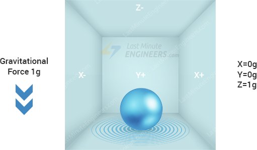
In this case the box isn't moving just we still get a reading of 1g on the Z axis. This is because the gravitational force is pulling the ball down with forcefulness 1g.
The accelerometer measures the static dispatch of gravity in tilt-sensing applications as well as dynamic acceleration resulting from motion, shock, or vibration.
How MEMS Accelerometer Works?
MEMS(Micro Electro Mechanical Systems) accelerometer consists of a micro-machined structure built on top of a silicon wafer.
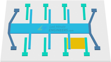

This construction is suspended past polysilicon springs. It allows the structure to deflect at the fourth dimension when the acceleration is applied on the item centrality.
Due to deflection the capacitance betwixt fixed plates and plates fastened to the suspended structure is changed. This change in capacitance is proportional to the acceleration on that axis.
The sensor processes this modify in capacitance and converts it into an analog output voltage.
How Gyroscope Works?
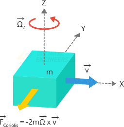
While accelerometers measure linear dispatch, MEMS gyroscopes measure angular rotation. To do this they measure the force generated by what is known equally The Coriolis Effect.
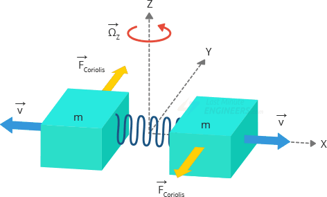
Coriolis Effect
Coriolis Outcome tells united states that when a mass (grand) moves in a detail management with a velocity (v) and an external athwart rate (Ω) is applied (Red arrow); the Coriolis Effect generates a strength (Yellow arrow) that causes a perpendicular deportation of the mass. The value of this displacement is direct related to the angular charge per unit applied.
At present suppose that there are two masses that are kept in abiding aquiver motility so that they motility continuously in opposite directions. When athwart rate is practical, the Coriolis effect on each mass is too in opposite directions, which results in a modify in the capacitance betwixt them; this alter is sensed.
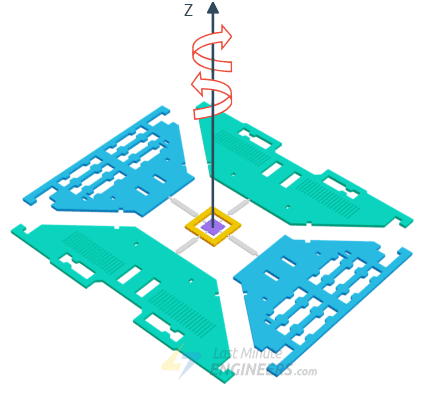
How MEMS Gyroscope Works?
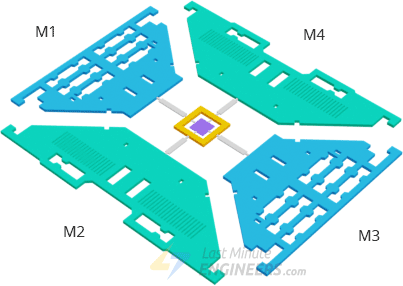
The MEMS sensor is composed of a proof mass (containing 4 parts M1, M2, M3 and M4) which is kept in a continuously oscillating motility then that is reacts to the coriolis outcome. They move inward and outward simultaneously in the horizontal plane.
When we start rotating the structure, the Coriolis forcefulness acting on the moving proof mass changes the management of the vibration from horizontal to vertical.
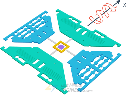
At that place are three modes depending on which axis the angular rotation is practical.
Scroll Mode:
When an angular rate is practical forth the X-centrality, due to the coriolis effect, and then M1 and M3 will motion upwards and down out of the plane. This causes the scroll angle to modify hence it is called Roll Mode.
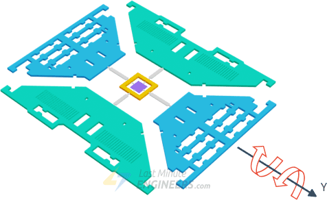
Pitch Manner:
When an angular charge per unit is practical along the Y-axis, and then M2 and M4 volition move upwardly and down. This causes the pitch bending to change hence information technology is called Pitch Mode.
Yaw Fashion:
When an angular rate is practical along the Z-axis, M2 and M4 will move in the aforementioned horizontal plane in opposite directions. This causes the yaw angle to change hence it is called Yaw Manner.
Whenever the coriolis effect is detected, the continuous move of the driving mass volition cause a capacitance change (∆C) which is picked up by the sensing construction and then converted to a voltage indicate.
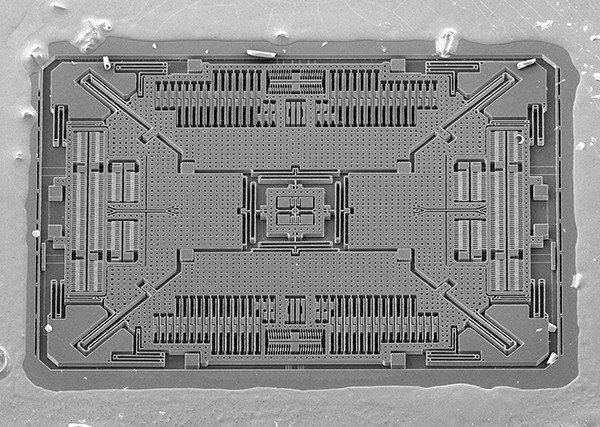
Just for your information this is what a MEMS structure die of a 3-axis digital gyroscope looks like. Thank you to Adam McCombs for sharing image of decaped L3GD20HTR MEMS gyroscope from ST Microelectronics.
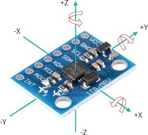
MPU6050 Module Hardware Overview
At the heart of the module is a depression power, inexpensive 6-axis MotionTracking chip that combines a 3-axis gyroscope, 3-centrality accelerometer, and a Digital Motion Processor (DMP) all in a small 4mm x 4mm bundle.
It can measure angular momentum or rotation forth all the iii axis, the static dispatch due to gravity, as well as dynamic acceleration resulting from motion, shock, or vibration.
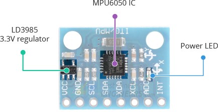
The module comes with an on-board LD3985 3.3V regulator, so you can use information technology with a 5V logic microcontroller like Arduino without worry.
The MPU6050 consumes less than 3.6mA during measurements and only 5μA during idle. This low power consumption allows the implementation in battery driven devices.
In add-on, the module has a power LED that lights upwardly when the module is powered.
Measuring Acceleration
The MPU6050 can measure acceleration using its on-chip accelerometer with iv programmable total calibration ranges of ±2g, ±4g, ±8g and ±16g.
The MPU6050 has three xvi-scrap analog-to-digital converters that simultaneously sample the iii centrality of movement (forth X, Y and Z axis).
Measuring Rotation
The MPU6050 can measure athwart rotation using its on-chip gyroscope with four programmable full scale ranges of ±250°/s, ±500°/s, ±1000°/s and ±2000°/s.
The MPU6050 has another 3 16-bit analog-to-digital converters that simultaneously samples 3 axes of rotation (around X, Y and Z axis). The sampling rate tin can be adjusted from 3.9 to 8000 samples per 2d.
Measuring Temperature
The MPU6050 includes an embedded temperature sensor that tin mensurate temperature over the range of -forty to 85°C with accuracy of ±i°C.
Note that this temperature measurement is of the silicon die itself and not the ambient temperature. Such measurements are commonly used to get-go the calibration of accelerometer and gyroscope or to detect temperature changes rather than measuring absolute temperatures.
The I2C Interface
The module uses the I2C interface for communication with the Arduino. It supports two split I2C addresses: 0x68HEX and 0x69HEX. This allows two MPU6050s to be used on the aforementioned bus or to avoid accost conflicts with another device on the bus.
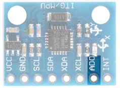
The ADO pin determines the I2C accost of the module. This pin has a congenital-in iv.7K pull-down resistor. Therefore, when you lot exit the ADO pivot unconnected, the default I2C address is 0x68HEX and when you connect it to three.3V, the line is pulled HIGH and the I2C address becomes 0x69HEX.
Adding External Sensors
To increase the level of accuracy even further, the MPU6050 module provides a characteristic for connecting external sensors. These external sensors are continued to the MPU6050 via a second I2C bus (XDA and XCL), which is completely independent of the main I2C bus.
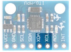
This external connexion is usually used to attach a magnetometer, which can measure magnetic fields on three axes. By itself, the MPU6050 has vi Degrees of Freedom (DOF), three each for the accelerometer and the gyroscope. Calculation a magnetometer adds an extra three DOF to the sensor, making it nine DOF.
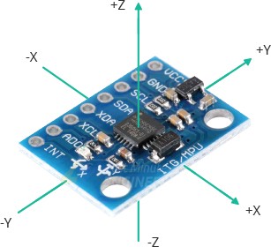
MPU6050 Module Pinout
The pivot descriptions of the MPU6050 module are every bit follows:
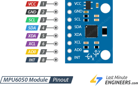
VCC is the power supply for the module. Connect it to the 5V output of the Arduino.
GND should exist continued to the ground of Arduino.
SCL is a I2C Clock pin. This is a timing signal supplied past the Bus Chief device. Connect to the SCL pivot on the Arduino.
SDA is a I2C Data pin. This line is used for both transmit and receive. Connect to the SDA pivot on the Arduino.
XDA is the external I2C data line. The external I2C omnibus is for connecting external sensors.
XCL is the external I2C clock line.
AD0 allows you to change the internal I2C accost of the MPU6050 module. Information technology can be used if the module is conflicting with another I2C device, or if you wish to employ ii MPU6050s on the same I2C bus. When you exit the ADO pin unconnected, the default I2C address is 0x68HEX and when you connect it to iii.3V, the I2C accost becomes 0x69HEX.
INT is the Interrupt Output. MPU6050 tin be programmed to enhance interrupt on gesture detection, panning, zooming, scrolling, tap detection, and shake detection.
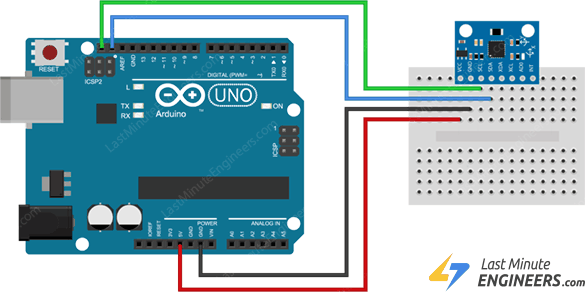
Wiring MPU6050 Module with Arduino
Connections are fairly uncomplicated. Start by connecting VCC pin to the 5V output on the Arduino and connect GND to ground.
Now nosotros are remaining with the pins that are used for I2C communication. Annotation that each Arduino Lath has different I2C pins which should be connected appropriately. On the Arduino boards with the R3 layout, the SDA (data line) and SCL (clock line) are on the pin headers close to the AREF pin. They are also known as A5 (SCL) and A4 (SDA).
If you lot are using a different Arduino board, delight refer below table.
The following diagram shows you how to wire everything.
Library Installation
The MPU6050 module is relatively easy to get upward and running and capturing the raw data output of the device. Manipulating the data into something meaningful, however, is more of a challenge, only in that location are some libraries available for using the device.
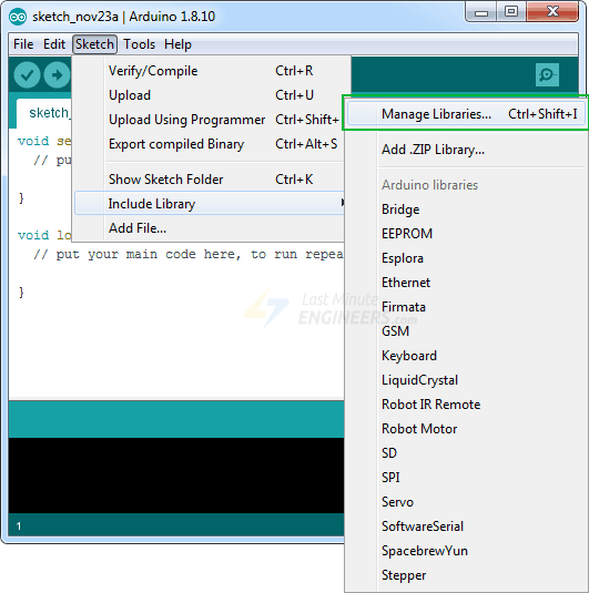
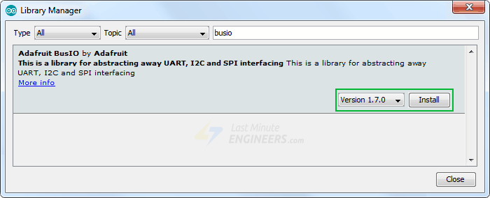
To install the library navigate to the Sketch > Include Library > Manage Libraries… Wait for Library Director to download libraries index and update list of installed libraries.
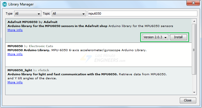
Filter your search by typing 'mpu6050'. At that place should be a couple entries. Look for Adafruit MPU6050 Library by Adafruit. Click on that entry, and then select Install.
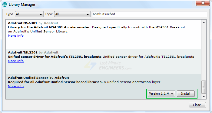
The Adafruit MPU6050 library uses Adafruit Unified Sensor Driver and Adafruit Bus IO Library internally. Therefore, search the library manager for Adafruit Unified Sensor and BusIO and install them likewise.
Arduino Code – Reading Accelerometer, Gyroscope and Temperature Information
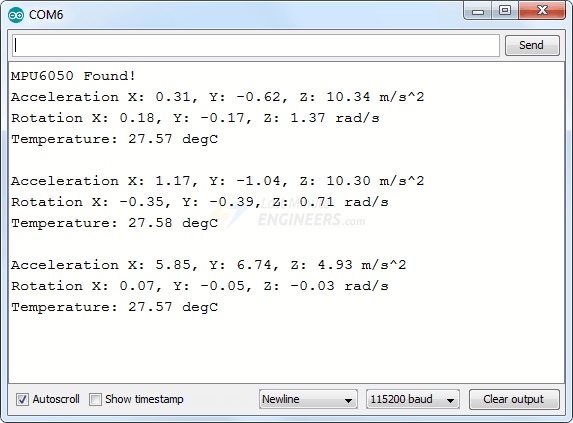
When y'all accept everything hooked up effort running the below sketch. It will give you a complete understanding on how to read linear dispatch, angular rotation & temperature from the MPU6050 module and can serve as the basis for more practical experiments and projects.
#include <Adafruit_MPU6050.h> #include <Adafruit_Sensor.h> #include <Wire.h> Adafruit_MPU6050 mpu; void setup(void) { Serial.begin(115200); // Try to initialize! if (!mpu.begin()) { Serial.println("Failed to find MPU6050 chip"); while (1) { delay(10); } } Serial.println("MPU6050 Found!"); // set accelerometer range to +-8G mpu.setAccelerometerRange(MPU6050_RANGE_8_G); // gear up gyro range to +- 500 deg/s mpu.setGyroRange(MPU6050_RANGE_500_DEG); // set filter bandwidth to 21 Hz mpu.setFilterBandwidth(MPU6050_BAND_21_HZ); filibuster(100); } void loop() { /* Become new sensor events with the readings */ sensors_event_t a, g, temp; mpu.getEvent(&a, &g, &temp); /* Print out the values */ Serial.print("Acceleration 10: "); Serial.print(a.acceleration.ten); Serial.impress(", Y: "); Serial.impress(a.dispatch.y); Serial.impress(", Z: "); Series.print(a.acceleration.z); Serial.println(" m/south^2"); Serial.print("Rotation X: "); Series.print(thou.gyro.x); Serial.print(", Y: "); Series.print(chiliad.gyro.y); Serial.print(", Z: "); Serial.impress(g.gyro.z); Serial.println(" rad/s"); Series.impress("Temperature: "); Serial.print(temp.temperature); Series.println(" degC"); Serial.println(""); filibuster(500); } Note that you must set your serial monitor to a speed of 115200 baud to try out the sketch. Considering too much data is sent back from the MPU6050, information technology requires this higher speed to brandish it.
You volition see myriad of data displaying linear acceleration, athwart rotation and temperature values. Try moving your sensor around and notice how the data changes.
Code Caption:
The first footstep is to include all the required Arduino libraries. As mentioned earlier, the Adafruit_MPU6050 library implements the hardware functions of the MPU6050 and the Adafruit_Sensor library the unified sensor abstraction layer. Y'all volition also need to include the Wire library, which comes pre-installed in the Arduino IDE. This library allows us to communicate with I2C devices.
#include <Adafruit_MPU6050.h> #include <Adafruit_Sensor.h> #include <Wire.h> Next, a new case of the Adafruit_MPU6050 course is created so that we can access related functions.
In the setup department of the code, we first initialize the serial advice with PC and telephone call the begin() role. The begin() function initializes I2C interface and checks if the chip ID is right. It then resets the chip using soft-reset & waits for the sensor for calibration after wake-up.
Serial.begin(115200); // Try to initialize! if (!mpu.brainstorm()) { Serial.println("Failed to notice MPU6050 chip"); while (1) { delay(x); } } Earlier using the device object you constructed, you must initialize it with the sensitivity range yous want to utilise. Below are three functions that set the measurement range of the MPU6050.
setAccelerometerRange(mpu6050_accel_range_t)
The setAccelerometerRange() function sets the accelerometer range. Immune values for 'setAccelerometerRange' are:
- MPU6050_RANGE_2_G – for ±2g range (default)
- MPU6050_RANGE_4_G – for ±4g range
- MPU6050_RANGE_8_G – for ±8g range
- MPU6050_RANGE_16_G – for ±16g range
Note that, the smaller the range, the more sensitive the readings will be from the accelerometer.
setGyroRange(mpu6050_gyro_range_t)
The setGyroRange() function sets the accelerometer range. Allowed values for 'setGyroRange' are:
- MPU6050_RANGE_250_DEG – for 250 degrees-per-2nd range (default)
- MPU6050_RANGE_500_DEG – for 500 degrees-per-second range
- MPU6050_RANGE_1000_DEG – for 1000 degrees-per-2nd range
- MPU6050_RANGE_2000_DEG – for 2000 degrees-per-2d range
Annotation that, a smaller degrees-per-second range means a more sensitive output.
setFilterBandwidth(mpu6050_bandwidth_t)
The setFilterBandwidth() function sets the digital low pass filter bandwidth options. Allowed values for 'setFilterBandwidth' are:
- MPU6050_BAND_260_HZ, – for 260 Hz bandthwidth (Docs imply this disables the filter)
- MPU6050_BAND_184_HZ, – for 184 Hz bandthwidth
- MPU6050_BAND_94_HZ, – for 94 Hz bandthwidth
- MPU6050_BAND_44_HZ, – for 44 Hz bandthwidth
- MPU6050_BAND_21_HZ, – for 21 Hz bandthwidth
- MPU6050_BAND_10_HZ, – for x Hz bandthwidth
- MPU6050_BAND_5_HZ, – for five Hz bandthwidth
The output data of the gyroscope are filtered by a low pass filter. The bandwidth pick allows yous to change the cutoff frequency of this filter. All the bandwidth setting does is simply smooth out the betoken a little by removing high frequency noise.
For our experiment we are setting the accelerometer range to ±8G, gyro range to ±500°/s and filter bandwidth to 21 Hz.
mpu.setAccelerometerRange(MPU6050_RANGE_8_G); mpu.setGyroRange(MPU6050_RANGE_500_DEG); mpu.setFilterBandwidth(MPU6050_BAND_21_HZ); The measurement range, or full-scale range, is the maximum acceleration or angular velocity that your MPU6050 can read. Remember about what you lot are measuring and set limits appropriately. Do you need to mensurate the spin of a record player (which is very slow) or a spinning wheel (which can be very fast)?
In the loop section of the lawmaking, we first create a sensors_event_t object in retention to hold our results. sensors_event_t is merely a user defined datatype (Structures in C) that holds many types of sensor data such as acceleration, gyro, temperature, low-cal, force per unit area and many more. Y'all can read more nearly it on github.
sensors_event_t a, thousand, temp; Adjacent, we call getEvent() function. This part reads a new set of values from you sensor (a sensor 'event'), convert them to the advisable SI units and scale, and and then assign the results to our mpu object. This is the function yous call to 'read' your sensor!
mpu.getEvent(&a, &g, &temp); Finally, we output the values on the serial monitor.
Serial.print("Acceleration X: "); Serial.print(a.acceleration.x); Serial.print(", Y: "); Serial.print(a.dispatch.y); Serial.impress(", Z: "); Serial.print(a.acceleration.z); Serial.println(" k/due south^2"); Serial.print("Rotation X: "); Serial.print(g.gyro.x); Series.print(", Y: "); Serial.impress(g.gyro.y); Series.print(", Z: "); Series.print(m.gyro.z); Serial.println(" rad/s"); Series.print("Temperature: "); Serial.print(temp.temperature); Serial.println(" degC"); Arduino Code – Plotting MPU6050 information
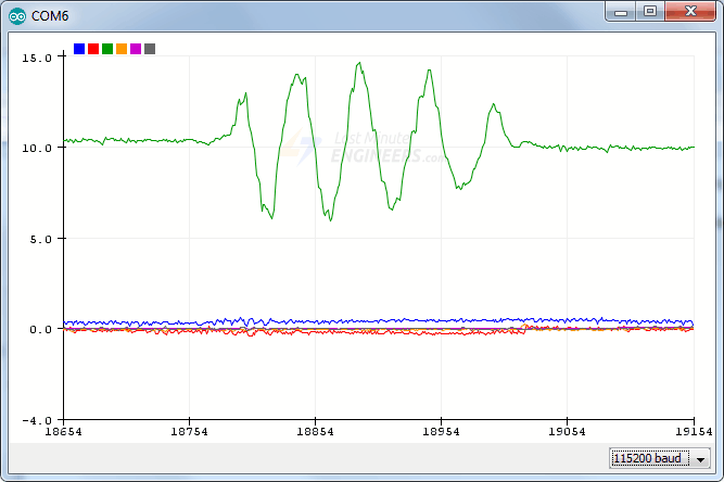
Simply looking at the raw data coming from the MPU6050 volition do nothing good. If yous really desire to encounter how your MPU6050 reacts when you motion it effectually, apply Series Plotter.
The Arduino IDE comes with a cool tool called the serial plotter. It tin can give you visualizations of variables in real-fourth dimension. This is super useful for visualizing data, troubleshooting your lawmaking, and visualizing your variables as waveforms.
Let's try information technology out with the new code below. Compile and upload the plan below, then navigate to Tools > Serial Plotter (Ctrl+Shift+Fifty). The code uses a baud rate of 115200, make sure it'due south set in the serial plotter as 115200 as well.
#include <Adafruit_MPU6050.h> #include <Adafruit_Sensor.h> #include <Wire.h> Adafruit_MPU6050 mpu; void setup(void) { Serial.brainstorm(115200); // Try to initialize! if (!mpu.begin()) { Serial.println("Failed to find MPU6050 chip"); while (1) { filibuster(ten); } } // fix accelerometer range to +-8G mpu.setAccelerometerRange(MPU6050_RANGE_8_G); // gear up gyro range to +- 500 deg/s mpu.setGyroRange(MPU6050_RANGE_500_DEG); // gear up filter bandwidth to 21 Hz mpu.setFilterBandwidth(MPU6050_BAND_21_HZ); delay(100); } void loop() { /* Get new sensor events with the readings */ sensors_event_t a, g, temp; mpu.getEvent(&a, &g, &temp); /* Print out the values */ Series.print(a.dispatch.x); Serial.print(","); Serial.print(a.acceleration.y); Series.impress(","); Serial.print(a.acceleration.z); Series.print(", "); Series.print(g.gyro.10); Serial.print(","); Serial.impress(g.gyro.y); Serial.print(","); Series.impress(1000.gyro.z); Serial.println(""); filibuster(10); } You should meet something similar this when moving the module up and downwards along the Z axis.
Lawmaking Explanation:
You lot will find that the majority of this sketch is exactly the same every bit the previous sketch, except:
- Temperature readings are not printed
- All other readings are printed such that it forms a comma-separated list of values
- The readings are taken every 10 milliseconds.
danielslonarterfes.blogspot.com
Source: https://lastminuteengineers.com/mpu6050-accel-gyro-arduino-tutorial/
Belum ada Komentar untuk "How Long Should It Take to Read an Mpu6050 With an Arduino"
Posting Komentar